|
This page was made to show just my Kustom Mods
Important: I appolagize for the crappy pics of ANY of my mods. The only digital camera I have is a JAM C@m,
and it sucks! I even edit the picture to make it look better before I post it on my site. They look WORSE before they're on
here. Crazy huh?
Memory Card Mod
An easy mod you can do if you own a PS2 Memory Card!
You put the little PSone logo from the top of a big grey PS1, and put it on you memory card. To do this, simply take 2
razors, stick one underneath the PS logo and peal a little. Put the other in for support, and slowly pry the logo off. Make
sure not to peal any color off with the razor. Color should not come off with the glue underneath. There should be enough
glue on bottom to stick right to the top a PS2 memory card torwards the bottom away from where it plugs into the system. Simple,
and looks GOOD! Image is not of good quality at all, but you can still tell what it looks like. 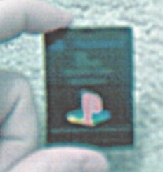
All the custom mods I've done to ONE
Dreamcast console
1. Door open/closed switch, with red LED indicator "on" light
2.
Green LED in back of modem, below the phone "line in"
3. Blue LED in
fan vent for cool effect
4. "Audio/Video in" using RCA jacks
5. Orange
LED in controller. Same color and MCD as the DC's, but smaller.
6. 4 AAA battery
pack for one VMU
7. 9 volt batter connector for other VMU. I use a half dead 9
volt. Puts out about 6 volts.
8. Headphone jack in back. Amp still to be added.
9.
Built "Dreamcast Current Indicator and Power Transmitter" to distribute
all power for my extra LED's and stuff.
10. Painted the DC's controller port faceplate,
power and open buttons, and little triangle on cover all light blue. My DC is going
to have a nice blue scheme.
Mods soon to do...
1. Change the DC's LED to a
bright blue, and use the orange one for my PS2 somehow.
2. Longer lasting
internal battery... maybe. Really no need, yet.
3. Audio "in" like
my other DC "had" before it broke. A headphone type jack that pops out
the side where you can plug a cd player into while playing a game for music. That's
also a maybe. I really don't want to screw with everything just to get to the board.
That's how I screwed up my last DC. Played with soldering and tinkering too much.
Name: Kyle Riffel
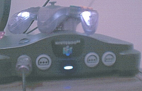
Platform: Nintendo
64
Model: N/A
Mod Chip: N/A
Pic: kyle_n64.jpg
Description:
My new N64 system with a bright blue power LED, and 2 white LED's in the clear purple
controller's handles. The neat thing about my N64 is that my new blue LED I installed
actually fades in upon start up. Unlike the original red LED that lit up as soon
as the system was turned on. The new blue LED takes about 1 sec. to light up, but
it fades real quick. I almost can't explain it. You turn the N64 on, it takes a sec.
for the LED to START lighting up, but another sec. for it to fade all the way. It's
just neat. The white LED's in the controller are a nice addition when you play in
the dark.
The hardest part was getting the gamebit screws out. I had to melt
the tip of a pen, and place on the screw until it dried hard, then remove the screw,
one by one. I replaced all the gamebits with phillips head screws once I was done
so I could easily get in again when I need to.
Name: Kyle Riffel
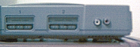
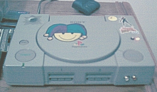
Platform: PlayStation
Model:
SCPH-7501
Mod Chip: Yes
Pic: kylepsx1.jpg
| kylepsx2.jpg | kylepsx3.jpg
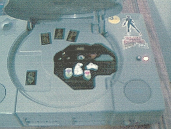
Description:
My PlayStation with a open/closed door switch with red LED indicator "on"
light. The LED lights up when the switch is on. This is the same open/closed door
switch I did with my DC, but doesn't look as good in my opinion. I would have liked
to put the switch on the side of the system like on the DC. But the vents are on
the side, not solid plastic. Still looks good, and is really useful.
I
also installed some RCA audio "in" plugs on the front of the system. Reason
unknown. I was bored. I would like to add a video RCA jack so I can plug in my PS2
to the PSX, then the PSX to the DC, then from the DC to the TV. Everything plugged
into the TV at the same time via a "daisy chain."
There a many stickers on the system too. A big smiley face
with jester's hat on. A bullet hole sticker over power supply. Tomb Raider III logo below Lara Croft sticker. PSM magazine
smiley face sticker. And on the inside of the system there is a "cute" bunny scene on the laser housing, and the word RAP
spelled out with mailbox stickers.
Directions: N/A
Name: Kyle Riffel
Platform: Saturn
Model:
MK-10000
Mod Chip: No
Pic: saturn_batterypack
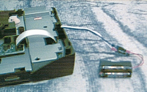
Description: Hooked
up a AAA
battery pack to the Saturns internal battery solder points. Why? So, when the batteries
die, they can easily be replaced with 2 more AAA's, instead of those expensive, hard
to find VMU type batteries.
Directions: On the Tips and Tricks page!
Name: Kyle Riffel
Platform: Dreamcast
Model:
HKT-3020
Mod Chip: No
Pic: dc_skyblue1.jpg
Description:
Painted my Dc's power and open buttons, front controller face plate, and the tiangle
above LED all skyblue. Color actually a little lighter than in pic. Looks great!
Can't wait until I get my blue LED in there.
Directions: N/A
Name: Kyle Riffel
Platform: Dreamcast
Model:
HKT-3020
Mod Chip: N/A
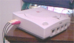
Pic: dc_rca0.jpg
| dc_rca1.jpg
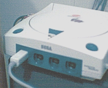
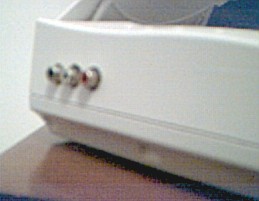
Description: I said
"Screw it!" to the 1/4 in. headphone jacks used as audio/videio "in".
I put the old RCA jacks back in, and they work better than ever! I needed my PS2
and DC both connected to one TV, so it works as a switch box sort of, w/o the switch.
Directions:
N/A
Name: Kyle Riffel
Platform: Dreamcast
Model: HKT-3020
Mod Chip:
No
Pic:
test_jack_1.jpg | test_jack_2.jpg
| jack_3.jpg | jack_4.jpg
| jack_working.jpg
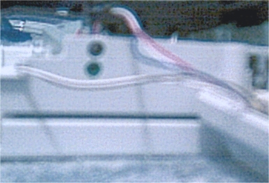
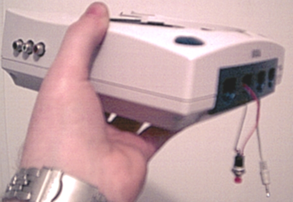
Description:
Dreamcast with two 1/4 in. female headphone type jacks used as an "audio/video
in". This was specially designed just for me. I had to splice the PS2's AV cord
to fit a 1/4 in. male connector to fit the female end put into the DC's side by power
board. The first two pics, test_jack_1, and test_jack_2 were accidents. I accidently
put the two jacks to close, and the male connectors wouldn't both fit at the same
time. So, I left the green jack in for a later headphone jack mod, and put the 2
jacks on the side by power board. This mod is similar to my 3 RCA jack mod on my
earlier DC. *Insight of future mods* --I'm saving those old RCA jacks for my PS2
mod! Works awsome!
Directions: N/A -When I feel like making a tutorial.
For now, it's my little secret!
Name: Kyle Riffel
Platform: Dreamcast
Model:
Mod chip installed: No
Pic: door_light1.jpg
| door_light2.jpg
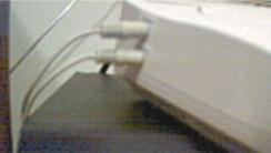
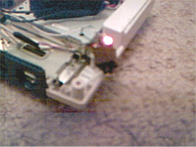
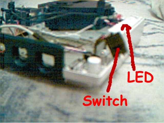
Description: A
LED hooked up to my "door open/closed" button that lights up when on, not
on when button is off. Just to let me know when I have the "open/closed door"
bypass on.
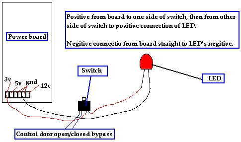
Directions: Your going to need a button with 4 connections.
One set for positive connections, other for lights connection. A PlayStation power
board button is great. That's what I used.
Your switch will need to be hooked
up for your door open/closed bypass which will take 2 of the 4 connections already.
The
other two are for the LED's pos. connection. Hook one end of wire from 3 or 5 volt
point on power board, to one side of switch. Hook another wire from other switch
connection, out to pos. of LED.
The neg. connection of LED should go straight
from power boards gnd. to the LED's neg. Here's a diagram for connection... door_light_diagram.jpg
Name: Kyle Riffel
Platform: Dreamcast
Model:
HKT-????
Mod chip installed: No
Pic: av_diagram.jpg
| rca_dc1.jpg | rca_dc2.jpg
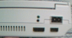
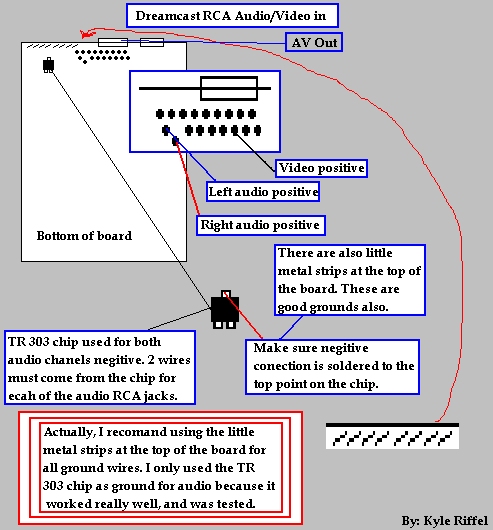
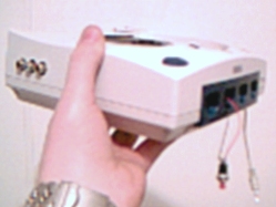
Description:
Dreamcast with Audio/Video jacks on the side by power board. Use: To be able to connect
your Dreamcast, and another device such as a PS2 into one TV that only has one set
of RCA jacks. (yellow, red, and white connections).
Directions: (Notice:
Before you begin this mod, know that it will take a good degree of electrical, and
proper tool knowlege. You will also need good, steady hands for the solder points,
and good drilling techniques."
You will need:
1. Soldering iron with
rosin core solder
2. Thin wire, 6 peices. (3 ground, 3 positive)
3. Drill with
bits
4. DC board
5. 3 small mountable RCA jacks (I recommend yellow for video,
red for right audio, and white for left audio. Radioshack has many types to choose
from. Must be small, because we cannot have interference from other componets in
DC.
6. Snips to cut thin metal.
7. Steady hands, many things can go wrong in
a project like this.
First of all, just remove everything from the system.
I am not going to go through each peice to remove. Put all small parts in a sandwhich
baggy or something. We need the DC board.
This is the easy part of the mod.
First, we'll solder the neg. connections. If you look at the bottom side of the board,
you can see little strips of metal going along the top. If your confused, look at
the diagram. av_diagram.jpg Any of
these are good negitive connections. Not good if you use one strip for all 3 neg.
though. The video pos. will connect by the AV Out area. There should be a bunch of
little solder dots behind it. Your spot is the 3rd from the right on the bottom set
of dots. The audio connections are the 2 that are off center form the rest. Confused?
Look at the diagram.
Now, for a little something more challenging. We need
to drill holes for our 3 RCA jacks to fit in. You can place these were ever you want
were they will fit. I put them on the side by power board. Now, we need to solder
the other end of our wire to the RCA jacks. Test before you solder first. Best thing
to do is just tape or wrap the wire around the solder points on the RCA jacks, then
plug something in. This is to make sure you know which point on the jacks are pos.
and neg. Usually, the center point is pos. and the outter point is neg on RCA jacks.
USUALLY!
After all this, solder them on, and test again with a PS2 or DVD
player to make sure. Now we can mount our jacks to their holes in the system with
a screw for the mountable type, or what I did, just super glue it on. I used a good
amount of glue though. I might go back and put screws in for a desgin look, and more
support. What the hey? Questions, e-mail me...synthetic_ky@hotmail.com
Name: Kyle Riffel
Platform: Dreamcast
Model:
Mod chip installed: No
Pic: dcaudio_0.jpg
| dcaudio_1.jpg | dcaudio_2.jpg
| dcaudio_3.jpg
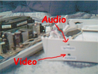
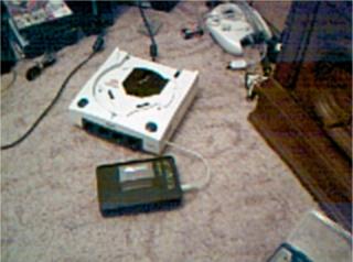
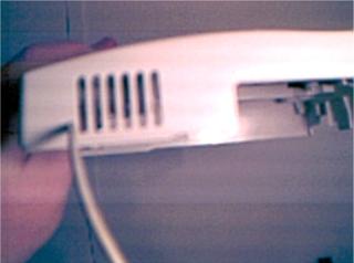
Description:
Dreamcast with headphone type connection to hook a cd player, radio, MP3 player,
anything to my Dreamcast, and hear the sound throught he system. The really cool
thing is, you don't have to have the DC on, or plugged in for that matter. Really
cool.
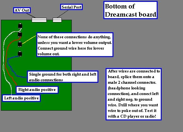
Directions: Before you begin... There are other ways to connect
left and right audio to your Dreamcast. My way is the safest, and easiest to do.
If you do not feel confident enough to solder the points in this document, refer
to the following diagram for an alternative left and right audio connection... alternate_dcaudio.jpg
There is also a connection to allow a video signal to be sent through your DC out
to the TV. But that's another mod. (Notice: This is just a BETA mod. It has only
been tested by just connecting AV cord to board, and turning on a CD player. It has
not been tested "in game" because my controller board is ruined, and it
won't let DC turn on without controller board installed. Because of fan. I am working
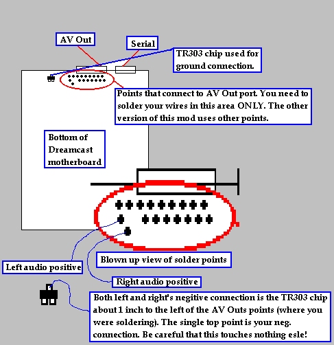
on a temp. controller installment just to test this mod.) Here is a diagram of where
the left audio, right audio, and both channels ground wires connect to... dcaudio_diagram.jpg
This will be reffered to through out the directions.
Tools you will need...
1.
Soldering iron
2. Rosin Core solder
3. Drill and bits
4. Phillips head screwdriver
5.
Dreamcast motherboard
6. Three 6-8 inch. thin wire (white-left channel, red-right
channel, and any other color for ground.
7. 2 channel male connector (type of
connector on headphones that plug into a CD player.)
8. Electrical tape
9.
Sissors
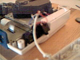
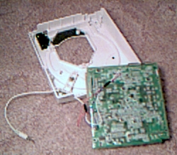
First of all, remove 6 screws from bottom of DC. Remove all internal
parts... Power Supply, laser and board assembly, controller port, with fan, and heat
sink on top of motherboard. The direction the motherboard is facing as it sits in
console is not what you want for this mod. Flip it over. (Note: When soldering, put
a cloth under motherboard to ensure it is not damaged on the surface you will use.)
Locate
the four 3 pin chips close by AV Out connector. I don't have a picture, so see the
diagram above for approx. location. The very top one we need to solder the left audio
to. I used white wire, because left audio is usually accomodated to white. We need
to solder the right pin of the top chip. Next chip down, we solder red wire (right
channel), to the right side pin of chip.
The next chip down is the video chip,
we do not need this chip. You would only use this chip to add a video feed. (My next
mod)
The chip below the video chip is your ground. We need to solder the LEFT
side pin on the bottom of this chip. Make sure it is the left pin! The right pin
is nothing that has to do with sound, *hint hint - wink wink.*
You need to
strip the male connector down to bare wires on the tip for splicing. Now, drill a
small hole only big enough to slip the end of you male connector that is cut so it
fits. But first, tie a not in the male connector so it CAN NOT be pulled through
from the outside once assembled.
Next, splice the male 2 channel conector
to the right spots on the soldered wires. Since we only have one ground, make sure
that both the left and right audio's negitive wire goes to this wire. My male connector
only had one ground for both, so it worked without flaw, but those using a male connector
off a broken pair of headphones or something will have 2 negatives. Anyway, you'll
want to put solder on each splice to make sure it doesn't disconnect, then wrap each
wire with electrical tape. Since we won't see the actual splice spot, don't worry
if it looks unatractive.
Before reassembling, we always test! All you need
to do to test it is plug in the AV cord, and plug a CD player into your new connection.
Turn the volume up on the CD player, and the volume up on your TV. If you hear both
left and right audio, your good. If not audio, check your ground, then left, then
right. Still no sound? Check your splicing. Maybe thw ires came undone. That's why
I said solder them. Remember?
Name: Kyle Riffel
Platform: Dreamcast
Model:
HKT-3020
Mod chip installed: No
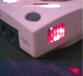
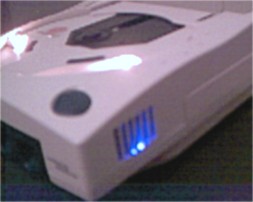
Pic: Old orange LED | New blue LED
Description:
Same Dreamcast I've done all my other mods to! Orange LED from the controller port
put on top of the fan's vent. Looks cool! Bright little orange light, with the shape
of the plastic bars from the case! That LED broke, so I installed a 5 volt blue LED onto the vent. I was going to put a 3
volt, but the 5 volt blue was cheaper than a 3 volt one. Personally, I thought the orange one looked betterm but, you gotta
do what you gotta do.
Directions: Little long, but worth
it.
Tools:
1. Phillips head screwdriver
2. Soldering iron
3. Rosin Core
solder
4. Electrical tape (optional)
5. Drill and bits
You need to remove
the 4 screws from the bottom of the Dreamcast system. I recomend putting all extra
parts and screws in a sandwhich baggy or something to keep them safe. Remove top
cover, and look at the fan. Remove the 2 or sometimes 3 pin fan wire, and remove
the 2 screws holding the fan on, just for precaution so you don't ruin the fan. Then,
remove the 2 screws holding the black vent in front of the fan that directs the air
torwards outside. Put all these parts in a safe place. Get ready to drill. You'll
want to start off with a small bit, so it can get through the plastic easier, without
breaking it. Then, slowly climb up to the size that the LED will fit perfectly. Note:
You might want to off center the LED. Not off center left and right, that would look
stupid, but make the LED closer to the fan. You get a little more light and pattern
from it. Plus, the heat from the LED will make it outside easier.
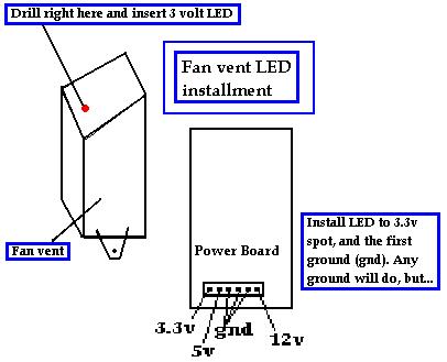
Next, run
the wire from the LED, to the 3.3 volt spot on the power board, and the first ground.
It doesn't matter which ground, but I used the first one. You might want to get a
LED that runs 3.3 volts or 3.5v for direct current from power board to LED or one
that runs 2.8 volts with the use of a 1/2 volt resistor connected to the positive
wire leading to LED. The 1/2 volt resistor will drop current 0.5v, so 3.3v - 0.5v
= 2.8v. You can get a 5 pack of 1/2 volt resistors from Radio Shack for like $0.99.
Cheap. Solder the wires to the prongs on the LED, and if you want, solder the other
end of the wires straight to the power board. I didn't do this, I just placed wires
in board holes, then snapped the board back on, and they hold tight. Place LED in
hole, and pack the wire down. I placed the wire under the controller board so it
didn't interfere with other mod wires like my 12 volt lights, and 5 volt blue LED.
You can either tape wire down with electrical tape, good insulator, or super
glue it down as a last resort. Or choose to just pack the wire under something like
the controller ribbon. Either way. Enjoy. Here is a diagram of the steps in easy
form. vent_diagram.jpg
To
tell you the truth, my first LED, the original one from the controller port got broke
because I had 3.3 volts running through it, and it's only a 3 volt LED. It started
blinking like crazy, (like a strobe light) and I thought it was shorting out, so
when I tried to tighten up the wires on the actual LED connection itself, I tore
one of the little prongs off. Ohh well, my new one will work fine when I get one.
Name: Kyle Riffel
Platform: Dreamcast
Model:
HKT-7700
Mod chip installed: No
Pic: dc_control_led1.jpg
| dc_control_led2.jpg
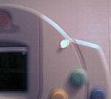
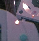
Description:
Dreamcast controller with orange LED by top right. Looks really cool. Exact same
orange color as DC LED. Another thing that's cool, it takes a couple seconds after
turning DC on before it turns on. Gives an initialization effect.
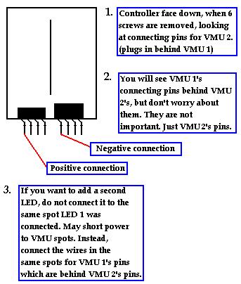
Directions:
Remove the 6 screws from the bottom of a DC controller. With it face down, look at
the small metal pins that connect to where the VMU's and rumble packs connect. The
big one on the left side of the poair of pins on the left is the positive (+) connection,
and the big one on the left, on the right pair of pins is the negitive connection
(-) for the LED. If you dont understand, here's a diagram of what it looks like.
vmuled_diagram.jpg There are actually
more little pins on a real controller than my diagram shows, but you only need the
use the 2 big ones on the left of each pair. I have no pic of the inside because digital camera makes it blurry. And I can't
fix it.
Name: Kyle Riffel
Platform: PlayStation®
Model:
1001
Mod chip installed: No
Pic: black_bluepsx1.jpg | black_bluepsx2.jpg
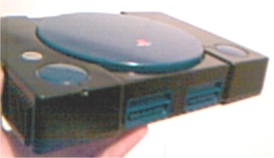
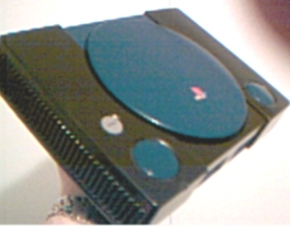
Description:
(Test console, used for practice.)
PlayStation system body painted black. Memcard
port, cd cover, open and power buttons all painted darkblue. Bullet hole sticker
on top of power supply like other system.
Directions: Remove all 5 or 6 screws from the bottom. My model is 1001, so
it only had 5 screws. You'll want to remove the PS logo from the sytem cd cover first, or you'll most likely forget it later,
like I almost did. I removed all buttons, and hinges. Or, everything that connected to the system. I pealed the model sticker
on bottom off, then removed the power light clear plastic thingy. I don't kow how I did it, but it just popped right off.
I tried that on a different system case, and it broke, so it was luck. Just be careful.I cleaned the system good. Let it
dry, then painted it in layers. I painted the cover, buttons, and mem card port in dark blue. And the top and bottom body
peices in black. I also painted the laser top blue. Looks good. Pic is of system before it final paint job. So, it looks better,
and has all peices back on. You'll see that the buttons are missing in the pic. They were still drying at the time.
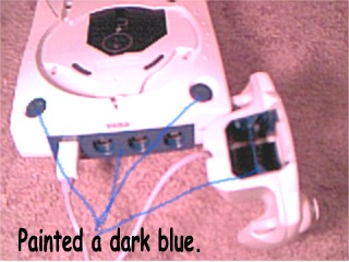
Update!!!
DC buttons and panels have been painted a dark blue. No lid yet, but once I get my clear lid, and paint the triangle dark
blue, the lights will shine though on start-up, W/ style! dreamcast_darkblue_mod.JPG
Name: Kyle Riffel
Platform: Dreamcast
Model: HKT-3020
Mod chip installed:
Soon
Pic: dc_light_mod.jpg | dc_light_on.jpg
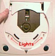
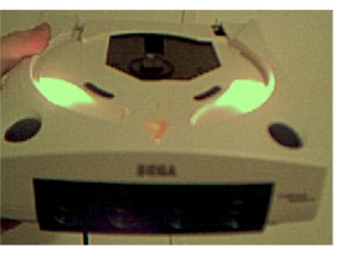
Description:
Dreamcast with
2 lights custom fit inside by laser assembly. No biggie, but different. I got bored,
and found some 12 volt lights. WILL look cooler when I get my clear blue top. Pic isn't that good, but better than nothing.
At least you know where the lights are.
Directions: Open system by removing all 4 screws. Locate the power supply.
Find where it says 3.5 volt, 5 volt, gnd gnd gnd 12 volt. You want to connect your light to the 12 volt, and the 3rd gnd.
I did it by pulling the power supply out, inserting the wires in the hole of the power supply, and making sure they went in
tight when the power supply snapped on the the 6 connections. Then you can drill the size of the light anywhere you want it!
A "Hope I get top do this, and I don't f*ck it up" mod...Name: Kyle Riffel
Platform: PlayStation®2
Model:
SCPH-39001
Mod chip
installed: No
Pic: N/A
Description: System tray painted blue. When you hit
eject, the tray is blue to add characteristic to the way it looks.
Directions:
Open system by removing all 8 screws from bottom. Remove the tray, and take off
the face plate on the tray that has the PS logo. Use spray paint in any color you
want. Cover whole tray with paint. Let sit over night. Snap front face plate with
PS logo back on. Put tray back in system, and close it up. Check it out! This kustom
job isn't that great, but it will make your PS2 look nice. I recomend using red,
blue or grey for the color of the tray. Those match up with the system pretty good.
|

