PlayStation
/ PSone Console Overclocking Guide
By: Kyle Riffel
I
felt compelled to write this guide after coming across a similar, yet not as
informative, guide by a Rob Ivy that ran Underground Console Mods, or www.ucm.com, which is now down… The guide
was for overclocking the PSX / PSone console from stock 33.6 MHz to 64 MHz, or
double CPU speeds! This guide wasn’t very informative, and left the user
wondering many things about the mod… Things like, where does this wire
go? And… How do you do this mod!?
I’m
being a little sarcastic, but the guide was weak in the information department.
It featured like 4 pictures with hard to see points, and everything based on
PIN numbers. At the time I didn’t know how to read PIN numbers on ICs. If
you don’t know how, use this… Look for the dot on the corner of the
IC. The closest PIN, usually to the left, is 1… When you get to the
bottom you go directly across, not back to the top and down! Easy…
I’ll also use pictures and diagrams to illustrate when necessary.
My Disclaimer
Please
do not steal, “borrow” or edit my tutorial. All information has
been checked, and double, double-checked. YES, two doubles! I absolutely
guarantee success in this mod if done correctly, although you will not receive
anything back but an e-mail probably if you have problems… J Since
the guide is free, you can’t return it for damages covered on some 90-day
risk free “warrantee…” I know, that’s a sad, but very
true joke… Anyway…
In no way do I
condone someone who doesn’t have experience in soldering to do
this. ALSO, if you are scared or “shaky” in the hands about lifting
a CPU PIN, then you need to STOP NOW! Lifting the leg on an IC is VERY risky.
Good thing it’s easy. Well kind of! I’ll have you know right now,
once lifted, just get it to raise enough to clear the other PINs, and LET IT
BE! Do not try to bend it back against the top of the IC as this MAY break it.
I bent mine back only because I’ve done this mod 4 times, and know when
the PIN will give!
Let’s Begin:
Now, there’s
actually two versions of this mod. One, you can have a switch that switches
from Oc’ed to normal mode. This guide will NOT demonstrate how to install
this switch. It requires soldering a wire from the lifted CPU PIN to the part of
the board that PIN actually touched before you lifted it. One side of the
switch will OC the console, or from lifted PIN to clock chip. The second mode
will connect lifted PIN to original place on board like stock.
::::What
You Will Need::::
- Soldering iron
- Thin wire: 22AWG or higher, 8” long TOPS
- Hot glue gun: REQUIRED (to hold lifted CPU PIN and soldered
on wire from moving!)
- Phillips head screwdriver
- Razor blade
- PlayStation / PSone console DUHH!
NOW Let’s Actually Start!:
Start
by disassembling your console. We need to get down to JUST the motherboard.
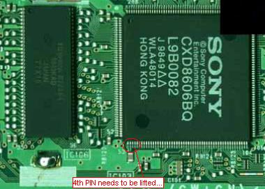
I’ll let you get there, its self explanatory. Locate CPU SONY, CDX8606BQ.
Turn the board so SONY reads going down, and so does the model number. The
fourth (4th) PIN from the left over needs to be lifted, like in the
picture below… Simply count from the left, 4… Take your razor
blade, and place it under the 4th PIN. Lightly apply pressure where
the blade would be pushing on the PIN from the bottom. NOTE: Other nearby PINs
will likely move too. Once the CPU PIN is lifted and out of the way, simply
adjust the other PINs that moved too.

Now, you need to locate your motherboard’s clock chip. This chip sends out a 64 MHz signal that gets divided by the CPU and another processor. I think it’s the graphics processor, RSX? Anyway… This 6 PIN chip is usually labeled “2194A”, or “2100 8858 JRC.” The lifted CPU pin needs to be linked with PIN 6 on the clock chip. Remember how to read IC PINs from the intro? That’s exactly how you find it. OR, you could just look at the following picture... And NO, the red dots do not mean solder here… That’s the origin of the line… I didn’t know what to type, so I just… Never mind…

The picture
shows the clock chip for two older model PlayStations, SCPH-7501 and SCPH-9001.
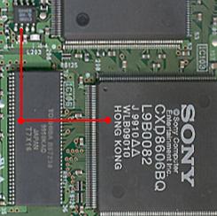
There is a rule of thumb I invented for finding the correct clock chip in case
it’s not labeled like above.
To locate the
correct clock chip if it’s not labeled “2194A”, or
“2100 8858 JRC,” simply look at the CPU labeled SONY, CDX8606BQ
like in the CPU picture. When you go directly to the left, you have your
systems memory. Directly above the system memory, you have your clock chip,
like in the diagram below…

You can either
solder directly to the IC, or to the solder point (pointed to in blue) on the
7501 console, and maybe other models too. Simply follow the trace in the board
and see if it leads to an obvious, and easy solder point. To do this, locate
PIN 6 on clock chip, and look for a light green trace going from this PIN, and
follow it to an easy solder point. DO NOT go past in-line components like
resistors and capacitors! IF you do not find an easy solder point, you’ll
have to solder to the IC itself. No biggie, it’s easy!
Once you make
connection to the CPU PIN, I HIGHLY suggest you hot glue the entire area round
the PIN so it cannot move! This PIN is VERY fragile! Hot gluing the clock chip
point is not necessary, but you can for insulation. I also suggest the line is
as short as possible for a good connection, and done with the heaviest gage
wire you can possibly solder this with, like 22 AWG. Maybe 20 AWG would work
too. Also if you can, I recommend a single strand wire, not wire with multiple
copper lines in it. This makes it quick and easy to solder without worry the
wire end will fray.
GOOD LUCK!
Special Thanks to Rob Ivy from Underground Console
Mods, www.ucm.com, for finding this hack.
Based on information I got from him, I was able to write this informative
tutorial.
:::Kyle Riffel::: a.k.a.
riva16