PS2 HDD Access LED Mod!
By: Kyle Riffel
This is one of the greatest looking mods you could do to your PS2 if you use the HDD for any reason, Final Fantasy 11, or to load games from HDD to play back at faster speeds. In any case, the number of LEDs and the way they are mounted make a major difference. I suggest 4 LEDs in the front vent, or 8 to fill the entire vent. In my case, there’s a 4” blue cathode tube in front of the HDD, so only 4 LEDs for this mod would fit. Looks great too!
What’s Needed:
- PlayStation2 motherboard V1-10 (should be compatible) New Slim model PS2 doesn’t support HDD, so no HDD access LED mod…
- Soldering iron
- Phillips head screwdriver
- Standard (flat head) screwdriver
- 470 Ohm resistor (or 5; 100 Ohm resistors)
- 4 – 8; 5mm LED’s (suggest ultra-bright LEDs rated for 3 – 3.3v)
- Thick wire for 12v current into resistor(s), thinner for current to LEDs and ground point
- Black tape
- Superglue
First Things First:
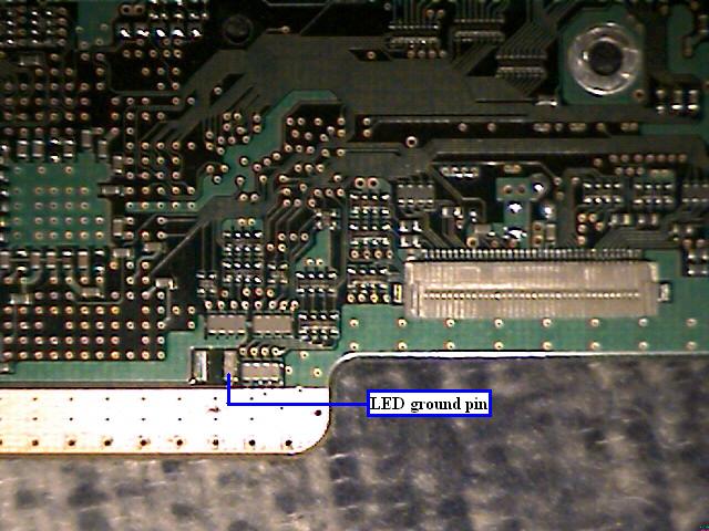
We will be patching power from the PSU, which only supports 12v lines, so 470 Ohms is perfect for bringing the 12v down to 3 – 3.3v, respectably. The trick tot his mod working is to use the original HDD access LED points. ONLY the ground point will be used, the “live” line will be left alone.
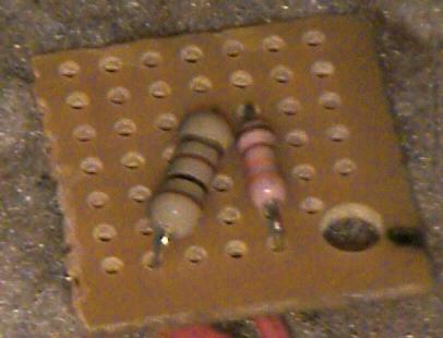
- Solder the 470 ohm resistor, (or 5 100 ohm resistors together) to the 12v line of the PSU. If you don’t know which lines are which, use this as a guide… Looking at the PSU from the bottom, where all solder points are, no components, WITH the plug that goes to the motherboard on the bottom right, the 2 far left points are “live” 12v lines, and the 2 far right points are both ground, (grounds in which we won’t be using.) TIP: Build a breadboard for the resistors if you are using 5 100 ohm resistors, that you can then glue to the PSU. If you’re using one 470 ohm resistor, just arrange the resistor where it can’t touch anything else, and glue it down, AFTER soldering on the next wire that goes to the LEDs!!!
- Off the 470 Ohms we need to solder 4 – 8 wires, (depending on how many LEDs you’re using) that run to each pos. (+) leg of each LED. Once this is done, use wire to link all the grounds together, twisting the wire tips into one lead for the motherboard soldering.
- Find the point in the picture, and solder the ground to this point. Every time the HDD is reading, or the head is moving, I can’t seem to figure out which is which, it flashes the ground accordingly, in which the ground your LEDs are soldered to. Translation: The LED’s flash!!!
- Simply erect the system together as much as needed in order to load FFXI, and/or you HDD program of choice, and see if the LEDs flash.
~MAKE SURE THE HDD IS CONNECTED BEFORE POWER UP FOR TEST! DO NOT PLUG IN THE HDD / NETWORK ADAPTER WHEN SYSTEM IS ON! IT WON’T WORK ANYWAY! TRUST ME!~
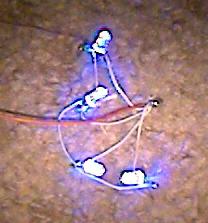
It works! You did it! Tape off the legs with black tape, and glue the LEDs where you want in the front vent or whatever by the bulb. Arrange all the wires where there’s no interference, and close the system up. Do a final test, and play a game! Watch the front vents explode in light EVERY TIME the HDD moves!
TIP: For a cooler effect; Use different colors for each LED… Something like red, orange, yellow, and white across the front vent… OR if you’re using 8 LEDs… red, orange, yellow, white, green, purple, aqua, and blue!
Looks even cooler than normal!